
7 Best Artificial Lift Pumps for Oil and Gas
Oil production increasingly depends on equipment that performs below the surface, under heat, pressure, and changing reservoir conditions. The IEA’s Oil 2024 report projects global oil demand will approach 104 million barrels per day by 2026. The Energy Institute’s Statistical Review also records more than 96 million barrels per day of global oil production in 2023. These volumes explain why reliable artificial lift pump selection matters beyond simple flow-rate comparisons.
As Gábor Takács, a recognized artificial-lift author and consultant, has emphasized, “Artificial lift is an integral part of the production system.” That principle guides this review of the seven best artificial lift pumps for oil and gas operations. The list considers pump efficiency, depth capability, gas handling, maintenance access, corrosion exposure, and lifecycle cost. Real wells are less tidy than brochures suggest. Reservoir pressure declines. Sand appears unexpectedly. Power availability changes. A pump that performs well in one field may struggle badly in another.
SPE technical literature consistently presents artificial lift as a production-optimization decision, not merely an equipment purchase. Electrical submersible pumps can deliver high rates, while sucker rod pumps often offer familiar maintenance practices. Progressive cavity pumps may handle viscous fluids effectively, but elastomer compatibility deserves careful checking. Hydraulic systems provide flexibility, yet surface infrastructure can become more demanding.
No ranking is universal. That is the uncomfortable part. Operators should verify laboratory data, field history, vendor assumptions, and total operating cost before choosing an artificial lift pump. Data matters. So does experience at the wellhead.
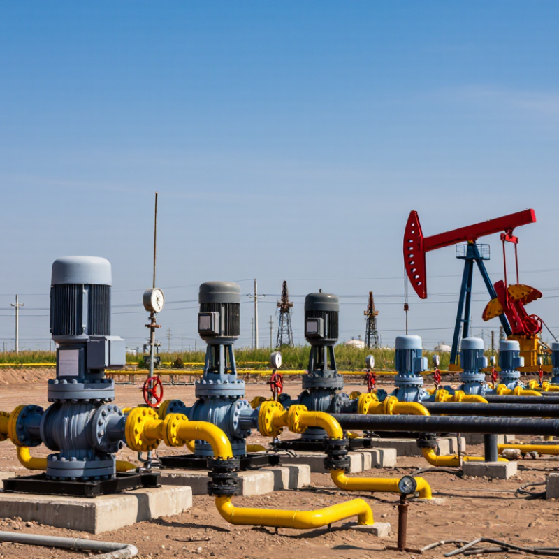
Rod Pumps: ~70% of Onshore Artificial-Lift Installations
7 Best Artificial Lift Pumps for Oil and Gas
Rod Pumps: ~70% of Onshore Artificial-Lift Installations
Rod pumps remain the workhorse of onshore artificial lift. Industry surveys and SPE technical literature commonly estimate that sucker-rod systems serve roughly 70% of onshore artificial-lift installations. The figure varies by basin, well age, and reporting method. It is useful, but not universal. The U.S. Energy Information Administration reports that artificial lift is essential across mature oil fields, where reservoir pressure cannot sustain economic flow. A walking beam moves the polished rod, transferring motion downhole through the rod string. The pump then lifts fluid, stroke by stroke.
Operators value rod pumps because they are visible, serviceable, and adaptable. A field technician can inspect polished-rod alignment, stuffing-box leakage, and pump-card behavior during routine visits. However, rod wear can increase in deviated wells. Gas interference may also reduce fillage and production stability. A 2023 SPE Production & Operations review noted that pump performance depends heavily on fluid properties, geometry, operating speed, and downhole conditions. More equipment is not always better. Poor sizing wastes power and accelerates failures.
Tips: Start with measured fluid level, gas rate, viscosity, and deviation data. Use dynamometer cards to identify mechanical loading before changing speed. Keep a failure log by depth and component. Small patterns often reveal larger design errors. Recheck assumptions after every workover.
7 Best Artificial Lift Pumps for Oil and Gas — Rod Pumps: ~70% of Onshore Artificial-Lift Installations
| Rank | Artificial-Lift System | Typical Production Range | Common Operating Depth | Fluid and Well Conditions | Main Advantages | Key Limitations | Best-Fit Application |
|---|---|---|---|---|---|---|---|
| 1 | Sucker-Rod Pump | Approximately 5–2,000 BOPD, depending on pump size, stroke, speed, and fluid properties | Commonly up to about 10,000 ft; deeper installations are possible with suitable design | Low-to-moderate gas, moderate solids, and light-to-heavy oil; requires a mechanically accessible wellbore | Established technology, straightforward surface inspection, flexible rate control, and broad field-service availability | Rod and tubing wear, gas interference, limited performance in highly deviated wells, and moving surface equipment | Conventional onshore oil wells with moderate production rates and stable operating conditions |
| 2 | Electrical Submersible Pump (ESP) | Approximately 500–30,000 BOPD, subject to pump design, fluid properties, and available power | Commonly about 3,000–15,000 ft, with high-temperature and high-pressure designs available | High liquid volume, water production, and relatively low-to-moderate free gas; solids and scaling require control | High liquid-rate capability, compact downhole installation, and strong performance in high-water-cut wells | Power-dependent, sensitive to free gas and solids, costly workovers, and exposure to temperature and electrical failures | High-rate wells where large liquid volumes must be lifted continuously |
| 3 | Progressive Cavity Pump (PCP) | Approximately 50–5,000 BOPD, depending on rotor size, speed, lift, and fluid viscosity | Commonly up to about 8,000 ft; actual depth depends on torque, elastomer, and rod-string limits | Viscous oil, emulsions, and moderate solids; free gas and high temperatures require careful selection | Good solids handling, low shear, efficient viscous-fluid lifting, and smooth variable-speed control | Elastomer compatibility and temperature limits, rotor/stator wear, and rod-string torque in deviated wells | Heavy-oil wells and wells containing sand or other abrasive solids |
| 4 | Hydraulic Jet Pump | Approximately 200–10,000 BOPD, depending on power-fluid rate, pressure, and well conditions | Often suitable for about 5,000–20,000 ft, subject to hydraulic design and friction losses | Deviated or offshore wells, variable fluid rates, moderate solids, and wells requiring pump-free completion access | No downhole moving parts, adaptable to changing rates, and retrievable by circulating or reverse circulation in suitable completions | Lower overall efficiency than many positive-displacement systems, requires high-pressure power fluid, and needs careful nozzle design | Remote, deviated, or high-temperature wells where intervention flexibility is important |
| 5 | Hydraulic Piston Pump | Approximately 100–5,000 BOPD, depending on piston size, power-fluid rate, and pump setting | Commonly about 5,000–20,000 ft, subject to hydraulic and completion constraints | Deep wells, moderate-to-high liquid rates, and applications where downhole mechanical equipment is undesirable | Suitable for deep installations, can handle changing well conditions, and has a retrievable downhole pumping assembly in many designs | Requires a reliable power-fluid system, can be less efficient than rod pumps, and may be affected by solids and fluid contamination | Deep or deviated wells requiring hydraulic power transmission from the surface |
| 6 | Plunger Lift | Typically about 10–300 BOPD, with gas and liquid rates varying widely by well and cycle design | Commonly used from shallow wells to more than 10,000 ft, depending on casing, tubing, and pressure conditions | Gas-rich wells with intermittent liquid loading, relatively low-to-moderate liquid production, and sufficient casing pressure | Low operating cost, limited downhole equipment, effective liquid unloading, and minimal external power requirements | Needs adequate gas energy, cycling can reduce steady production, and performance declines when reservoir pressure is too low | Mature gas wells and oil wells that experience periodic liquid loading |
| 7 | Gas Lift | Approximately 100–20,000 BOPD, depending on injection-gas availability, well geometry, and reservoir pressure | Commonly suitable for about 4,000–20,000 ft and for many highly deviated or offshore wells | High-gas-volume environments, high water cut, deviated wells, and fluids containing sand or corrosive components | Few downhole moving parts, strong tolerance of deviation and solids, and flexible rate control through injection adjustment | Requires compression and continuous gas supply, generally has lower efficiency, and may increase operating costs | Fields with available injection gas and multiple wells requiring centralized lift control |
Note: Production rates and depth ranges are representative engineering ranges, not guaranteed performance limits. Actual selection depends on reservoir pressure, inflow performance, fluid properties, gas fraction, water cut, solids, temperature, deviation, power availability, and workover strategy.
Related Posts
-
5 Best Artificial Lift Pumps Revolutionizing Oil Recovery: Boost Efficiency and Cut Costs
-
How to Optimize Production with Artificial Lift Pumps: Enhancing Efficiency in Oil Wells
-

Understanding the Impact of Artificial Lift Pumps on Oil Extraction Efficiency
-
What is an artificial lift pump and how does it work?
-
How to Optimize Artificial Lift Pump Efficiency for Better Production?
-
How to Choose the Right Artificial Lift Pump for Your Needs?